Learn how to use most features of circuitikz with many examples and explanations.
Introduction
As we learned in lesson 12, circuitikz is a powerful tool for circuit creation. But there are some pitfalls along the way. The circuitikz manual provides a nice reference for all components available, but lacks an in-depth explanation on how to use every element. Basically, there are three important types of components available in circuitikz, which are namely monopoles, bipoles and tripoles. The other components mentioned in the manual can be used in a way similar to the classes mentioned in this tutorial.
Lines
Before I step into the various components, let me show you how to change the appearance of the basic lines in circuitikz. Consider the following example:

\begin{figure}[h!]
\begin{circuitikz}
  \draw (-1,0) to[short,o-o] (1,0);
\end{circuitikz}
\end{figure}
As you can see, the syntax changed a little from the previous lesson. The first line is pretty much the same. The first line will draw the upper line segment with an open connector at each end. The connectors can be selected by changing the o-o part in the code.
If we’d like to change the connectors, consider the following example, which will lead to this output:

\begin{figure}[h!]
\begin{circuitikz}
  \draw (-1,0) to[short,*-] (1,0);
\end{circuitikz}
\end{figure}
The notation for connectors is pretty straightforward. You can choose the type of connector at each end of the line by using either the * or o symbol. Besides you can select that only one end or both ends of the line should have this kind of symbol e.g. o-, -o or o-o. If you don’t want a connector at all, simply write to[short] without any additional symbols.
Monopoles
I will start off with monopoles, which are about the most basic component of circuitkz. This class contains symbols such as ground nodes and antennas. So let’s take a closer look at an actual example.

\begin{figure}[h!]
\begin{circuitikz}
  \draw (-1,0) to[short,o-o] (1,0);
  \draw (0,0) to[short] node[ground] {} (0,-1);
\end{circuitikz}
\end{figure}
I took the line from the first section, but added a ground node to it. As you can see, the line differs in that the component is not specified as a bipole using the to operator, but as a node of type ground (node[ground]). It is imperative, that every node has a label in tikz. This label can be left empty, but the syntax should must be node[options] {}. If we decided to name our node, we could just write the text in between the braces such as

\begin{figure}[h!]
\begin{circuitikz}
  \draw (-1,0) to[short,o-o] (1,0);
  \draw (0,0) to[short] node[ground] {GND} (0,-1);
\end{circuitikz}
\end{figure}
That’s all there is to monopoles in circuitikz.
Bipoles
I’ve already covered bipoles in lesson 12, but I want to explain some more advanced features here. Most of the time, we want to have arrows to indicate current or voltages in our circuits. Circuitikz provides easy to use options to add these to your circuits. The examples here were basically taken from the circuitikz manual, so you can find some more examples in there, but I thought they shouldn’t be missing in my tutorial, since this is a very important feature.
Current arrows
The most basic way to add a current arrow to your bipole is by specifying the i option for the respective component. By default, the direction of the arrow and the position of the label are determined by circuitikz, but you can override those settings to enhance readability.

\begin{figure}[h!]
\begin{circuitikz}
  \draw (0,0) to[R,i=$i_1$] (2,0);
\end{circuitikz}
\end{figure}
If you wanted to change the direction of the arrow, you could simply use the following code instead. The < or > operator can be used to indicate the direction of the arrow.
\begin{figure}[h!]
\begin{circuitikz}
  \draw (0,0) to[R,i<=$i_1$] (2,0);
\end{circuitikz}
\end{figure}
Furthermore we can manipulate the position of the label $i_1$ by using either the ^ or _ operator, which stands for above and below the line. First look at the result for the first operator:

\begin{figure}[h!]
\begin{circuitikz}
  \draw (0,0) to[R,i^=$i_1$] (2,0);
\end{circuitikz}
\end{figure}
Now we want to place the label below:

\begin{figure}[h!]
\begin{circuitikz}
  \draw (0,0) to[R,i_=$i_1$] (2,0);
\end{circuitikz}
\end{figure}
The two kinds of operators can be combined to change the position of the arrow to either the left or right hand side of the bipole. To place the arrow on the left hand side, simply write

\begin{figure}[h!]
\begin{circuitikz}
  \draw (0,0) to[R,i<_=$i_1$] (2,0);
\end{circuitikz}
\end{figure}
and change the direction to place it on the right hand side like this

\begin{figure}[h!]
\begin{circuitikz}
  \draw (0,0) to[R,i_>=$i_1$] (2,0);
\end{circuitikz}
\end{figure}
Voltage arrows
The voltage arrows can be used in just the same manner as the current arrows, but this time, use the v option instead.

\begin{figure}[h!]
\begin{circuitikz}
  \draw (0,0) to[R,v_>=$v_1$] (2,0);
\end{circuitikz}
\end{figure}
As you can see, the same operators apply to manipulate position and direction of the arrow

\begin{figure}[h!]
\begin{circuitikz}
  \draw (0,0) to[R,v^<=$v_1$] (2,0);
\end{circuitikz}
\end{figure}
Labels
Of course it’s possible to add a label for the element itself as well. We do that by using the l option this time.

\begin{figure}[h!]
\begin{circuitikz}
  \draw (0,0) to[R,l^=$R_1$] (2,0);
\end{circuitikz}
\end{figure}
We might as well place the label below the element as well, again using the _ operator:

\begin{figure}[h!]
\begin{circuitikz}
  \draw (0,0) to[R,l_=$R_1$] (2,0);
\end{circuitikz}
\end{figure}
Tripoles
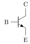
The last but not least group of components are tripoles. The most important group of tripoles are of course all kinds of transistors. You can find a whole list of examples for transistors along with this one in the circuitikz manual, but let me point out how the usage is different from bipoles.

\begin{figure}[h!]
\begin{circuitikz}
  \draw (0,0) node[npn](npn1) {}
  (npn1.base) node[anchor=east] {B}
  (npn1.collector) node[anchor=south] {C}
  (npn1.emitter) node[anchor=north] {E};
\end{circuitikz}
\end{figure}
Tripoles are nodes in circuitikz just like monopoles, but you have to place several anchors to the respective connectors of the tripole. First you specify a name for the node in parenthesis. In this case I’ve chosen the name npn1. This name will be used to reference to our transistor later on. Afterwards, the three anchors must be set as seen above.
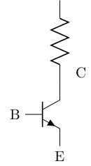
We can now refer to the nodes and attach some other elements to the transistor.

\begin{figure}[h!]
\begin{circuitikz}
  \draw (0,0) node[npn](npn1) {}
  (npn1.base) node[anchor=east] {B}
  (npn1.collector) node[anchor=south,xshift=0.5cm] {C}
  (npn1.emitter) node[anchor=north] {E};
  \draw (npn1.collector) to[R] ++(0,2);
\end{circuitikz}
\end{figure}
Note that I added an xshift option to the node, to prevent the label from overlapping with the new element. I hope you enjoyed my explanations and that you find using circuitikz a lot less confusing from now on.
Summary
- There are three main classes of components in circuitikz
- All other classes can be used in a way similar to those main classes
- Usage examples are provided in the circuitikz manual
Next lesson: